- Thu 19 September 2024
- Projects
- #arcade, #controller, #3d printing, #games
I'm a big fan of twin-stick shooters, particularly the older arcade and console games that predate analog control and use 8-way movement and shooting control. The most common way to play them today is with a standard game controller with two analog sticks, but I dislike analog sticks due to my dainty woman hands not being able to cope with the analog stick positions on most controllers for an extended period. Having designed and printed several arcade controllers of my own, I set out to create a controller that makes use of the several arcade levers in my spare parts bin, specifically my two Seimitsu LS-32-01s, and the large build volume of my 3D printer.
The Prize Winner is licensed CC-BY 4.0.
Model Downloads
- Prize Winner
- Arcade Bat Top with 24mm Swerry Button Thread
- Swerry Universal Cherry (and alike) Button 24mm Conversion
The Prize Winner model page includes an overhang test print with the same 30-degree overhang the main body has. Use this to determine the optimal printing orientation for cooling. On my printer, the Anycubic Kobra Max with a modded printhead with dual fans, I found that orienting the body along the Y axis will allow the fans to cool the part without moving.
Print Settings
- 0.6mm nozzle recommended
- 0.2mm layer height (0.3mm/0.4mm layer height for bottom plate)
- 8% or more infill
- 2 wall loops
- 2 top and bottom layers
- No supports (Vertical hole overhangs may sag at the top, but it will be covered by the button rims)
- Add mouse ears on the corners — OrcaSlicer has this feature built-in
Bill of Materials
These non-affiliate links are provided for convenience.
- RP2040-compatible microcontroller board
- Waveshare RP2040-Plus is used here, but any board supported by GP2040-CE with at least 28 GPIO pins will work
- 2 arcade levers of your choice, with hollow shafts
- Hollow shafts for popular Sanwa and Seimitsu models are available on Focus Attack
- 18x 24mm pushbuttons
- The Swerry Universal Cherry (and alike) Button 24mm Conversion can be printed instead, with keyboard microswitches of your choice—I used Akko V3 Silver Pro switches
- If keyboard microswitches are being used for the buttons:
- (Recommended) Ribbon cable, in place of standard stranded copper wire if soldering directly onto keyboard microswitches
- (Recommended) 30AWG wire wrapping wire, in place of standard stranded copper wire for chaining ground terminals
- 4x #10 countersunk machine bolts
- A size smaller than #10 may be used if your mounting plates require it
- 4x #10 lock washers
- 4x rubber feet with #10 bolt inserts
- 4x #10 machine bolts
- 8x #10 nuts, washers
- 8x 6mm x 3mm magnets
- (Recommended) Double-sided foam tape
- For the stick buttons:
- 4x spring terminals, or
- Audio cables and breakout boards:
- 2x TRRS breakout boards (Optional; any 3.5mm audio jack breakout boards will work if the rings will not be connected)
- Can be substituted with 3.5mm female audio cables
- 2x 3.5mm male 4-pole audio cables (Any 3.5mm audio cable will work; 4-poles optional)
- 2x TRRS breakout boards (Optional; any 3.5mm audio jack breakout boards will work if the rings will not be connected)
History
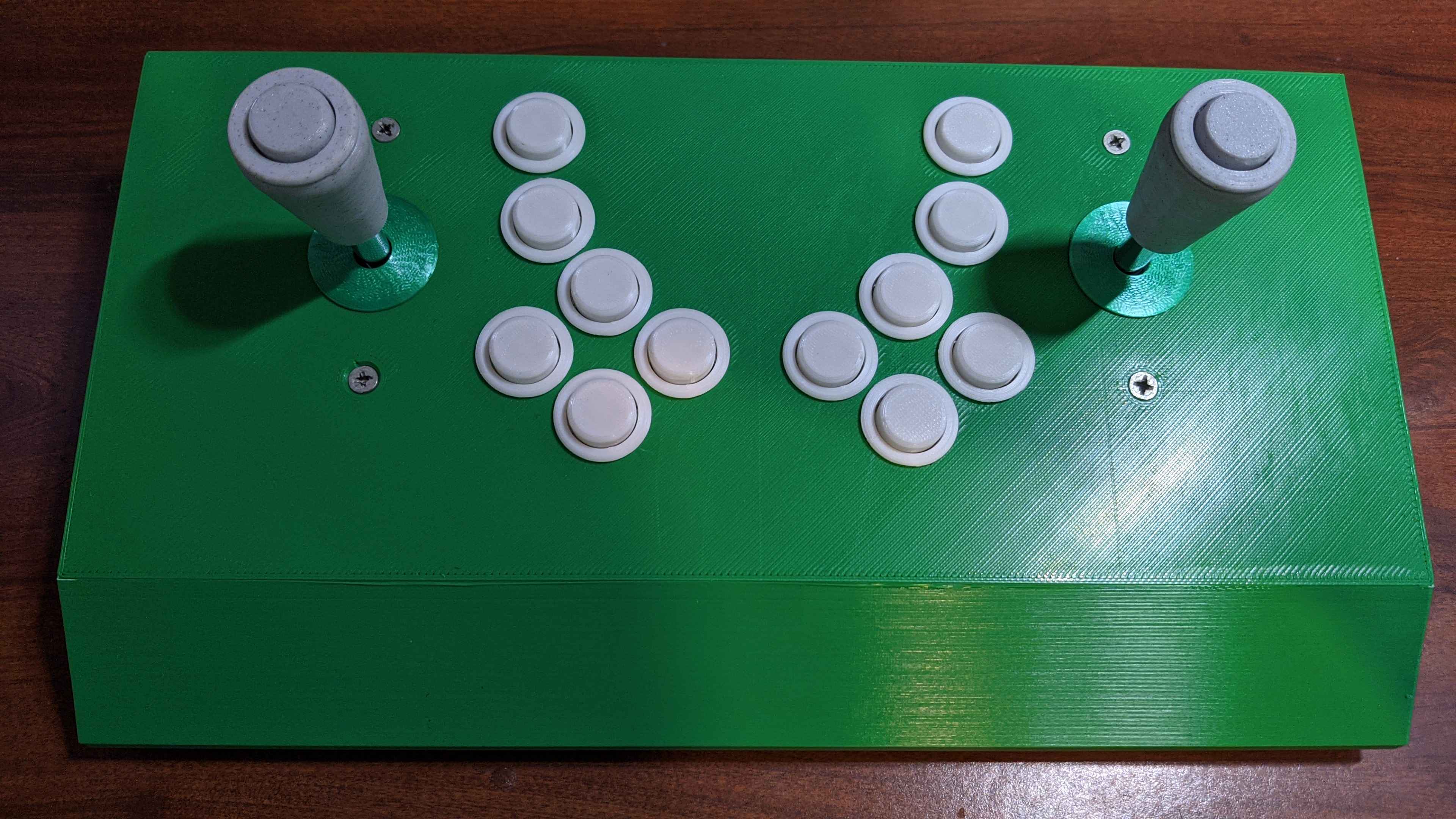
The Prize Winner is my attempt to create a box that contains two full-size levers and enough buttons to play twin-stick shooters. The model I am publishing is the fifth design iteration. It was originally conceived to play Smash T.V., hence the name alluding to the game show theme. I'm interested in competing in speedrun races of the SNES game, where the easy difficulty is the most popular category—runs are typically around 7 minutes long, making it ideal for race formats. With that said, I'm more interested in complete runs of the normal difficulty, and I think its sequel Total Carnage is the better game, so in my first prototype I added two buttons on the top for bombing—the Total Carnage arcade cabinet used a single button per player to both start a game and set a bomb. When it came time to consider using it to play newer games like Nuclear Throne and Enter The Gungeon, it quickly became clear that many more buttons would be needed for such functions as switching weapons, using character abilities, and checking a map.
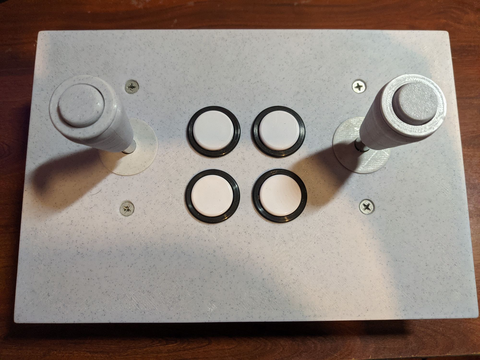
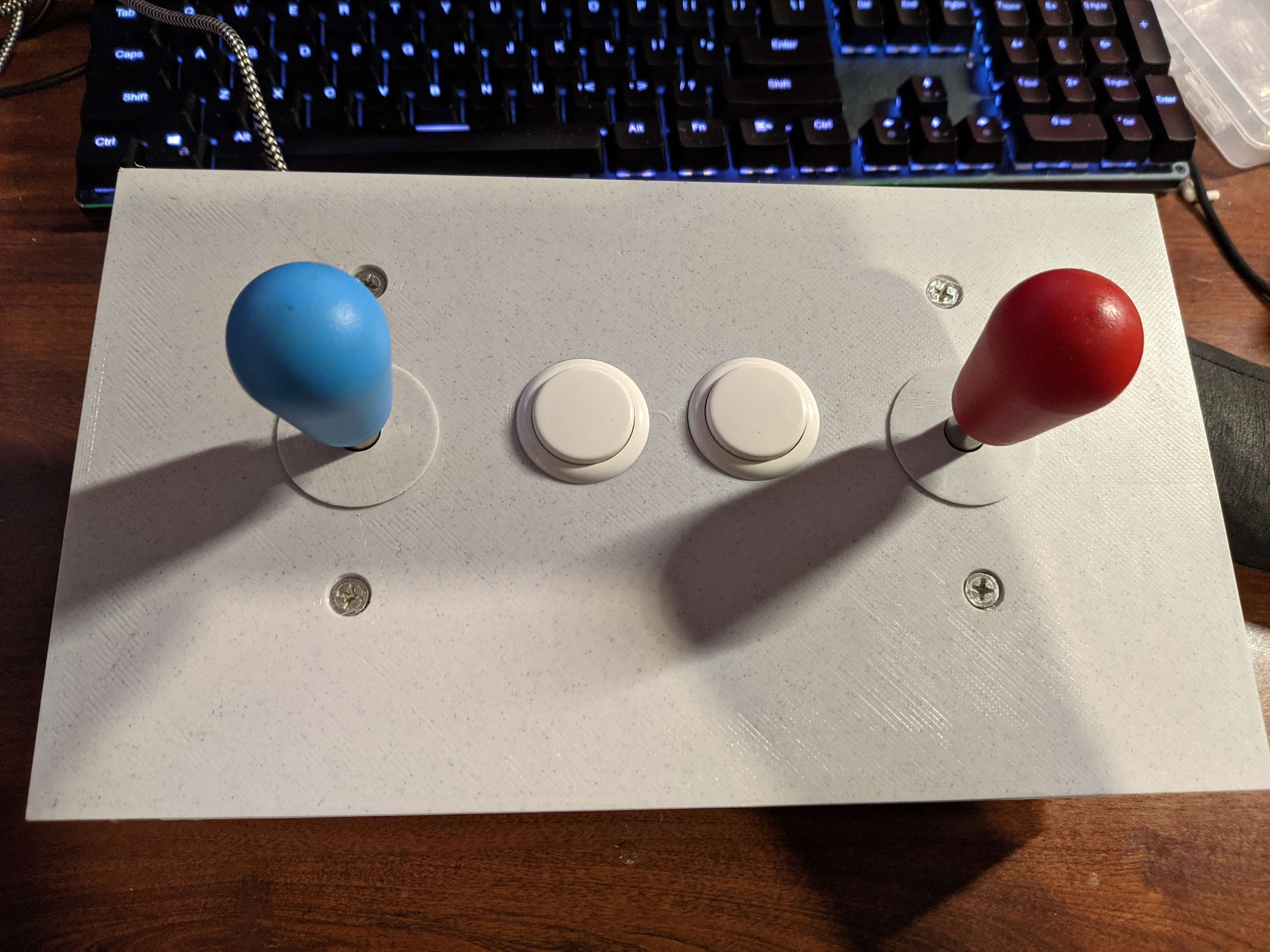
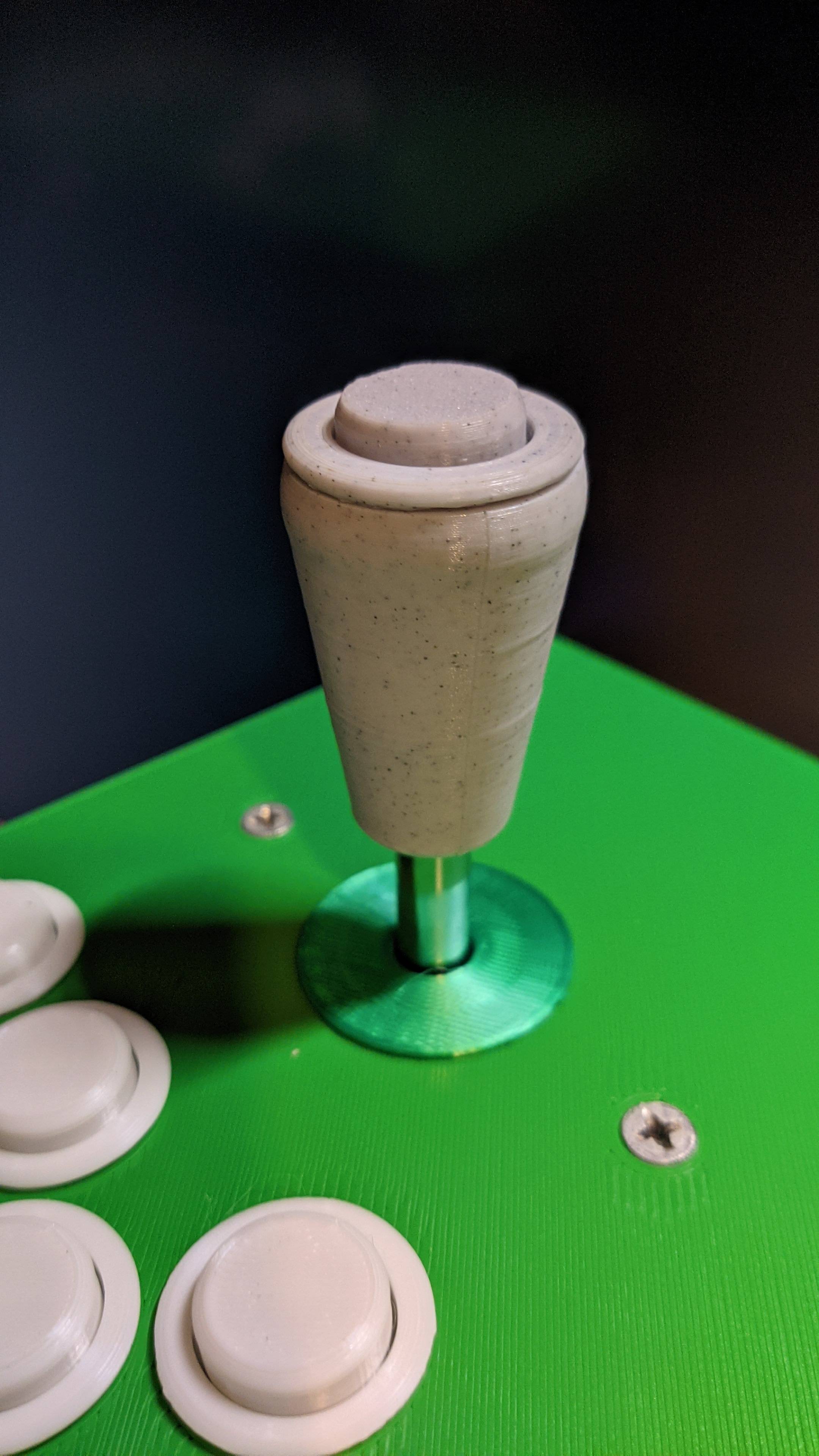
The second iteration had four buttons on the top panel for the face buttons. I also ordered hollow shafts, normally used to insert lights into a joystick top, for the LS-32 to allow for a button on the top of the battop, and for this I modified a battop on Thingiverse to change the tip to a threaded hole for a 24mm button. Unfortunately, I failed to consider that Enter The Gungeon also uses the D-pad, so I came to the conclusion that every button on a gamepad including the D-pad would need to be included one way or another.
Control Layout
This diagram shows the button layout I settled on with the third iteration, showing XInput and PS3 labels (the rest of this article will use XInput names):
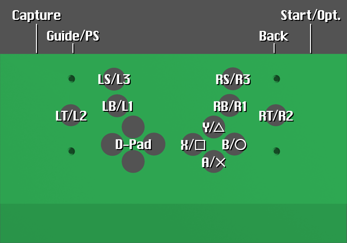
The top four buttons are for the shoulder buttons and stick buttons. I decided to put the triggers on the battop buttons since RT is most commonly used for firing weapons. Modern twin-stick games commonly use all of these controls as well as at least one face button, so I experimented with layouts to allow my fingers to reach all of them with minimal disruption. The shoulder and stick buttons are arranged with a vertical slant toward the edges of the box, within reach of my ring fingers. The D-pad and face buttons, arranged in a slightly wide diamond shape, are placed such that my thumbs can reach them, though it's necessary to tilt the sticks toward the inside. It sounds inconvenient, but in practice, when I play these games with a gamepad and use the face buttons, I would need to take my thumbs off the sticks and slightly tilt them anyway.
Design Challenges
Wires connected inside the lever, which can twist freely, will eventually twist enough to strain and potentially break the connections on either the button terminals or the PCB. To solve this, I needed a method to allow the cables to be disconnected and untwisted. My first solution was to splice Dupont connectors, but they cannot reliably stay connected with wires that are expected to move frequently. The permanent solution I decided on was to use a 3.5mm audio cable to wire the button, connected to a breakout board. This would allow me to easily disconnect the jack and spin it to correct any twisting whenever it became necessary.
I ordered a set of 4-pole TRRS audio cables and corresponding breakout boards, as my original plan was to design a new battop with a button thread on the top and two smaller buttons along the side like triggers on a flightstick. However, I wasn't able to come up with a stable design for this, so I'm using the single button and leaving the two rings unconnected for now. They can be hooked up as alternate inputs for the shoulder buttons and analog stick buttons if a new design can be created to solve this problem. To mount them inside the stick body, I printed simple 13mm x 13mm x 5mm cubes and used double-sided foam tape to affix the PCB to the cube and the cube to the body. The added height is more than enough to make removing the jack easy.
I had realized after completing the project that this can all be accomplished just as easily with wire terminals, specifically spring-loaded push terminals. I used audio cables because they are circular and can potentially self-correct, as well as being removable without tools. Spring terminals can also be corrected without tools, and they have the added advantage of allowing the wires to be easily removed from the shaft.
The last design challenge was to improve the ergonomics. I learned from designing the IMB that a 90 degree edge on a typical box will cut into players' wrists, so commercial arcade controllers usually have a bevel on the bottom edge. Because the body is printed upside-down, this bevel is a steep overhang. Most 3D printers can print overhangs up to 45 degrees, but the bevel I wanted to add is closer to 30 degrees from the print bed. The fourth iteration is where I attempted to add this, but while the rest of the print with the updated control layout printed fine, the overhang was unacceptable and had severe sagging. I printed it with silk green PLA, the color of money, and learned too late that silk PLA is elastic and needs special consideration when printing overhangs. I instead ordered standard green PLA and learned from some testing that steep overhangs are much more likely to print successfully when oriented on the Y axis, so the fans on the extruder can cool the part without moving along the X axis. I have also since switched from PrusaSlicer to OrcaSlicer, which has many more options to improve overhang printing.
My testing with the previous iterations also showed that the length of the body should be as wide as possible, because twisting the sticks causes the hands to move horizontally a surprising amount. My printer, the Anycubic Kobra Max, has a print volume of 400mm x 400mm x 450mm, and the Prize Winner model is 383mm x 210mm x 58mm. It is very close to the maximum length with mouse ears added on the corners, large enough that I had to forgo printing the skirt.
My fifth print was finally a success. However, there are two flaws. The first few layers of the overhang sag where my test print did not, most likely because I suspended the cooling fan for too many layers. Additionally, I accidentally made one of the countersink screw holes too large, though I have since corrected it in the STL.
Arcade and Electrical Parts
I had two Seimitsu LS-32-01 sticks in storage from earlier arcade controller projects, as I read in the early 2010s they're better for shmups. I use #10 machine bolts, washers, and lock washers to secure them into the body. Two body models are available: one includes standoffs beneath the screw holes for the LS-32-01 S-plate, and the other is flat.
For the rest of the controls, 24mm buttons are used. To save money, I decided to print my own buttons using my 24mm remix of the Swerry Universal Cherry Button model and keyboard microswitches. I settled on Akko V3 speed silver switches for optimal response time, though the battop buttons are currently using blue clicky microswitches from a disused mechanical keyboard.
The PCB is a Waveshare RP2040-Plus, a derivative of the Raspberry Pi Pico. The main difference is a USB-C port rather than a micro USB port, the sole reason I chose it over the several Pico boards I have on hand despite the higher price. It is supported by GP2040-CE. The Tilt Input add-on of GP2040-CE made this project possible, as it exposes both analog stick controls alongside the D-pad. However, as of version 0.7.9, a somewhat unintuitive configuration is needed.
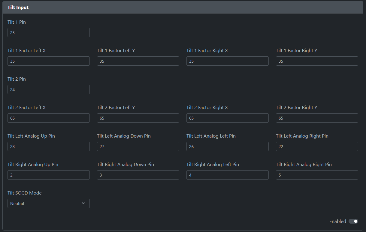
Before using this add-on, all other add-ons including the turbo inputs and the I2C pins must be set to -1 and disabled to enable remapping them in the Pin Mapping page. The Tilt Left Analog and Tilt Right Analog pins can be set to any digital GPIO pin on the board, but none of them will function unless the Tilt 1 and Tilt 2 pins are set above -1, even though they will be unused here. There are just enough pins on the stock RP2040 to allow for 8 tilt analog input pins and 16 button pins along with the 2 tilt pins to be left unused.
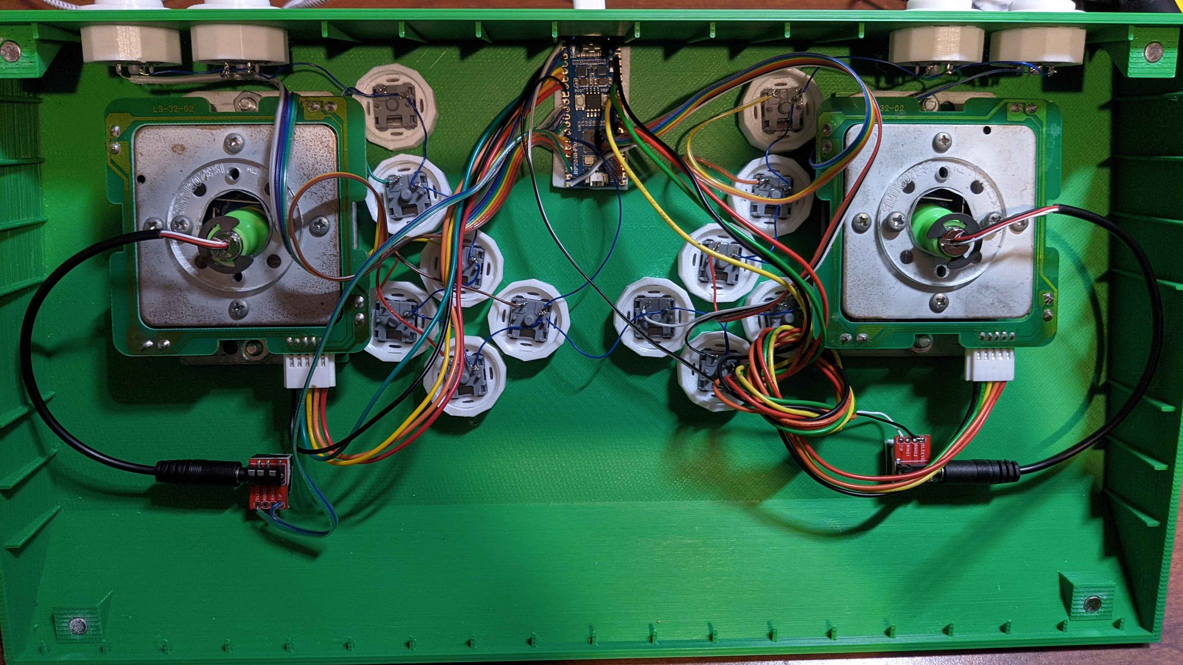
For wiring the buttons and joysticks, I simply connected the wires to the closest GPIO pins without regard for the original button layout. GP2040-CE allows all digital GPIO pins to be reassigned freely, though a button is needed on GP17 to access the web config facility before remapping. Since the button contacts need to be soldered on directly, I used generic ribbon cable to keep the connections together. I used 30AWG wire wrapping wire to chain the ground contacts together.
To install the battop buttons, strip enough of the audio cables such that around 1 inch of the wire can extend out of the button hole. This will make soldering the wires onto the button contacts easier. Quick disconnects may be used here if they can fit inside the cavity of the battop, but I haven't tested this.
After completing the soldering, I hastily mounted the RP2040-Plus into position with a strip of double-sided foam tape. There aren't any mounting holes on this board unlike the Raspberry Pi Pico, so my original plan was to use hot glue to fix it to the body. By the time I finished the wiring, it was past midnight, so I used the quickest method and it was enough to keep the board in place when connecting a USB-C cable.